A circuit breaker panel wiring diagram is a visual guide essential for safe electrical installations and troubleshooting․ It illustrates the layout and connections within the breaker panel, ensuring compliance with safety standards and proper functionality․ These diagrams are crucial for identifying components, understanding power distribution, and performing maintenance efficiently․ Always refer to a certified PDF diagram specific to your panel model for accurate information and adherence to electrical codes․ Safety precautions, such as turning off power and using testers, are vital before starting any work․ This guide provides a comprehensive overview to help you navigate and understand circuit breaker panel wiring diagrams effectively․
What is a Circuit Breaker Panel?
A circuit breaker panel is a central electrical component that distributes power to various circuits in a building․ It houses circuit breakers, which protect wires and devices from overcurrent conditions․ The panel acts as the main control point for electrical systems, allowing users to reset or disconnect power when needed․ It is a critical component for ensuring safe and efficient power distribution, and its proper installation and maintenance are vital for electrical safety and reliability․
Importance of Wiring Diagrams for Installation and Maintenance
Wiring diagrams are crucial for the safe and efficient installation and maintenance of circuit breaker panels․ They provide a clear visual representation of the electrical system, helping electricians identify components, connections, and potential hazards․ These diagrams ensure compliance with electrical codes and standards, preventing legal issues․ They also aid in troubleshooting by allowing quick identification of faults, saving time and effort․ Regular maintenance is simplified, as diagrams highlight the overall layout and potential weak spots․ Additionally, they serve as valuable educational tools for both professionals and DIY enthusiasts, promoting safe and correct modifications․ By following wiring diagrams, electricians can avoid accidents, ensure functionality, and maintain system reliability, making them indispensable in electrical work․
Key Components of a Circuit Breaker Panel
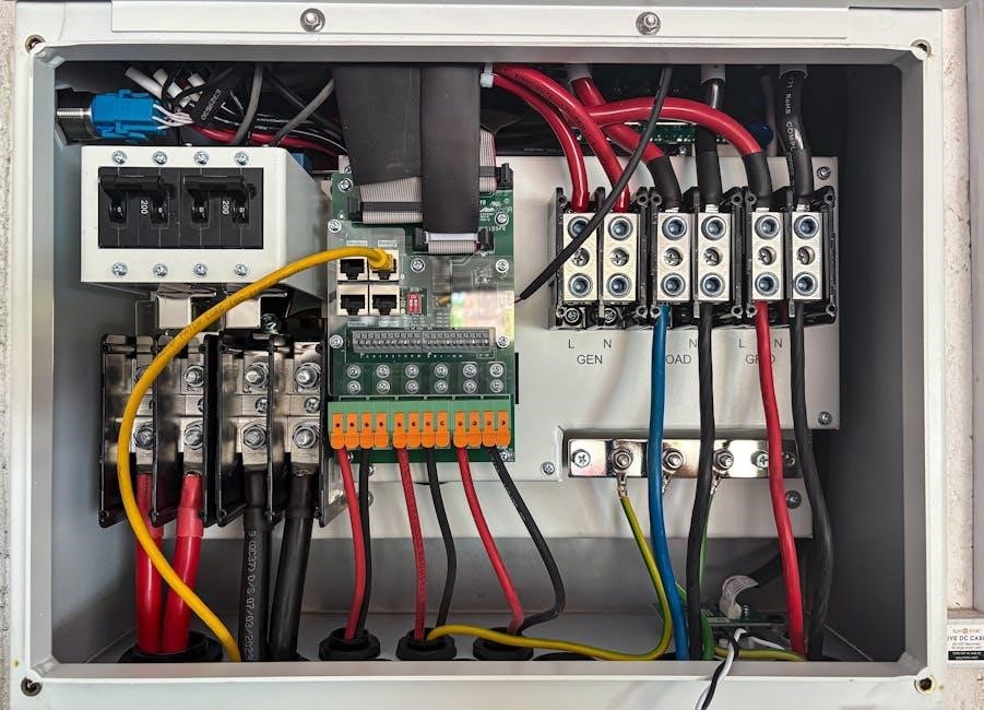
A circuit breaker panel consists of essential components like circuit breakers, main disconnect, bus bars, and ground wires․ These elements work together to distribute power safely and efficiently throughout a building, ensuring reliable electrical connections and protection against overcurrent conditions․ Proper installation and maintenance of these components are vital for system performance and safety․
Main Components of the Panel
The main components of a circuit breaker panel include circuit breakers, bus bars, neutral bars, and grounding terminals․ The circuit breakers protect individual circuits from overcurrent, while bus bars distribute power to all breakers․ Neutral bars connect to the neutral wire, ensuring proper circuit completion, and grounding terminals provide a safe path for fault currents․ These components are clearly illustrated in a wiring diagram, helping technicians understand the panel’s layout and connections for efficient installation and troubleshooting․
Types of Circuit Breakers and Their Functions
Circuit breakers vary in type and function, including standard breakers for general protection, GFCI (Ground Fault Circuit Interrupter) for grounding safety, and AFCI (Arc Fault Circuit Interrupter) to prevent arcing hazards․ Double-pole breakers handle higher voltage, while miniature circuit breakers are compact and versatile․ Each type serves specific roles in protecting circuits from overcurrent, ensuring safety and efficiency․ Wiring diagrams detail their placement and connections, guiding proper installation and maintenance for reliable electrical systems․
Understanding the Wiring Diagram
A wiring diagram is a visual representation of the circuit breaker panel, showing connections and components․ It provides a simplified layout of the electrical system, helping users identify key parts and their relationships․ This tool is essential for installation, troubleshooting, and maintenance, ensuring safe and efficient work․ Standard symbols and notations are used to represent wires, breakers, and other elements clearly․ Understanding these elements is vital for safe and effective electrical work․
How to Read and Interpret the Diagram
To read a circuit breaker panel wiring diagram, start by identifying the main components, such as the bus bars, circuit breakers, and ground wires․ Use the legend or key provided to understand the symbols and notations․ Trace each wire to its destination, noting the connections and any labels․ Pay attention to color coding, which indicates different types of circuits or voltages․ Always ensure the power is off before working on the panel, and refer to the diagram for troubleshooting or installations․ This step-by-step approach ensures safe and accurate interpretations․
- Identify components like bus bars and breakers․
- Use the legend for symbol meanings․
- Trace wires to their connections․
- Check color codes for circuit types․
By following these steps, you can interpret the diagram effectively and perform electrical tasks safely and efficiently․
Common Symbols and Notations Used
Circuit breaker panel wiring diagrams use standardized symbols to represent components․ Common symbols include circles for circuit breakers, lines for wires, and abbreviations like “L1” or “L2” for live wires․ Ground wires are often marked with a “G” or a grounding symbol․ Notations may include voltage ratings, wire gauges, and connection points․ These symbols ensure clarity and consistency, aiding in accurate installations and troubleshooting․ Refer to the diagram’s legend for specific definitions and meanings․
- Circles represent circuit breakers․
- Lines denote wires and connections․
- “L1” and “L2” indicate live wires․
- “G” or grounding symbols mark ground wires․
Safety Precautions and Best Practices
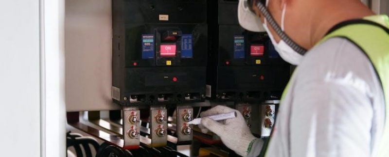
Always turn off the circuit breaker and verify power is off using an electrical tester before starting work․ Avoid operating without safety devices․ Ensure proper grounding and follow the wiring diagram instructions․ Never work on live circuits, and wear protective gear․ Adhere to local electrical codes and manufacturer guidelines for safe installation and maintenance․
Essential Safety Measures Before Starting Work
Before working on a circuit breaker panel, ensure all power is turned off and verify using an electrical tester․ Properly ground the system to prevent shocks․ Avoid operating without safety devices, and always follow the wiring diagram instructions․ Wear protective gear, including insulated gloves and safety glasses․ Never touch live circuits, and ensure all components are de-energized․ Double-check that the circuit breaker is off and locked out if possible․ Adhere to local electrical codes and manufacturer guidelines to ensure a safe working environment․
Common Mistakes to Avoid During Installation
Common mistakes include neglecting to turn off the power and failing to verify it with an electrical tester․ Improper connections and mislabeling circuits can lead to safety hazards․ Overloading the panel and ignoring proper grounding procedures are critical errors․ Always follow the wiring diagram and avoid working on live circuits․ Ensure all components are rated for the intended voltage and current․ Double-check connections before restoring power to prevent malfunctions and ensure compliance with safety standards․
Troubleshooting Common Issues
Common issues include tripped breakers, blown fuses, and miswired circuits․ Always consult the wiring diagram to identify faults and ensure proper connections․ Test for power before repairs․
Identifying Faults in the Circuit Breaker Panel
Identifying faults in the circuit breaker panel involves checking for tripped breakers, blown fuses, or loose connections․ Refer to the wiring diagram to locate the source of the issue․ Use an electrical tester to verify power at specific points․ Look for signs of overheating or arcing, which may indicate damaged components․ Always disconnect power before inspecting internal wiring to ensure safety․ This methodical approach helps pinpoint and resolve electrical problems efficiently․
Repairing and Replacing Damaged Components
Repairing damaged components begins with disconnecting power and verifying de-energization using an electrical tester․ Refer to the wiring diagram to identify faulty parts, such as breakers or connections․ Replace components with compatible, rated parts, ensuring secure connections․ Tighten all terminals properly and verify system functionality after repairs․ If unsure, consult a licensed electrician to avoid further issues and ensure compliance with safety standards․

Maintenance and Upkeep
Regular inspections ensure optimal performance․ Check connections, inspect components for wear, and verify wiring diagram compliance․ Address issues promptly to prevent faults․ Schedule periodic professional checkups․
Regular Checks to Ensure Optimal Performance
Conduct regular inspections to ensure your circuit breaker panel operates efficiently․ Verify all connections are secure and comply with the wiring diagram․ Inspect for signs of wear, overheating, or damage․ Test circuit breakers to ensure they function correctly․ Use an electrical tester to confirm power is off before servicing․ Replace any worn or damaged components promptly to maintain safety and performance․ Schedule annual professional inspections for comprehensive evaluations․
When to Call a Professional Electrician
If you encounter complex wiring issues or notice signs of malfunction, such as frequent tripping or overheating, consult a licensed electrician․ They can interpret your circuit breaker panel wiring diagram to identify faults and ensure repairs meet safety standards․ DIY attempts without expertise risk electrical hazards and non-compliance with regulations․ For major installations or upgrades, professional assistance is essential to guarantee reliability and adherence to local electrical codes․ Stay safe by seeking expert help when needed․
Legal and Compliance Requirements
Ensure your circuit breaker panel wiring diagram complies with local electrical codes and regulations․ Obtain necessary permits and certifications to guarantee safety and legal compliance during installation and maintenance․
Regulations and Standards for Electrical Installations
Electrical installations must comply with national and local codes, such as the National Electric Code (NEC) in the U․S․ or international standards like IEC․ Circuit breaker panel wiring diagrams must adhere to these regulations to ensure safety and proper functionality․ Design and installation should follow guidelines set by recognized organizations, such as Eaton or similar manufacturers․ Always consult certified professionals or official resources to meet all legal and technical requirements for your specific system․
Obtaining Necessary Permits and Certifications
Before starting any electrical work, obtain the required permits from local authorities to ensure compliance with regulations․Certifications from recognized bodies, such as UL or IEC, guarantee that components meet safety standards․A licensed electrician should handle installations to avoid legal issues․ Always complete inspections and obtain approval before finalizing the work․ Failure to comply may result in fines or system rejection․ Ensure all documentation aligns with NEC or IEC standards for validity․

Tools and Materials Needed
Essential tools include wire cutters, screwdrivers, and multimeters․ Materials like circuit breakers, wiring, and connectors are required․ Ensure all components meet safety standards for proper installation․
Essential Tools for Working with Circuit Breaker Panels
When working with circuit breaker panels, essential tools include a multimeter for voltage testing, screwdrivers for connections, and wire cutters for trimming wires․ A circuit tester ensures power is off, while a torque wrench secures breakers properly․ Pliers and insulated tools prevent electrical shock․ Always use tools rated for the panel’s voltage to ensure safety and compliance with electrical standards․ Proper tools are vital for accurate and safe installations․
Materials Required for Safe and Proper Installation
Key materials include high-quality copper wires, PVC conduit, circuit breakers, and bus bars․ Insulated wire nuts, grounding wires, and heat-resistant sleeves ensure safety․ Use durable wire connectors and cable ties for secure connections․ A junction box and appropriate fasteners are essential for mounting․ Always opt for materials meeting local electrical codes and standards to guarantee reliability and compliance․ Proper insulation and labeling materials are also crucial for clear identification and long-term performance․
Circuit breaker panel wiring diagrams provide a clear visual representation of electrical connections, ensuring safe and proper installations․ They detail component layouts, power distribution, and safety protocols․ Always use certified PDF diagrams specific to your panel model for accuracy․ Essential steps include turning off power, testing circuits, and adhering to electrical codes; These diagrams are vital for troubleshooting, maintenance, and compliance with regulations, ensuring reliable and hazard-free electrical systems․ Referencing them is crucial for both professionals and DIY enthusiasts․
Final Thoughts on Safe and Effective Installation
Safe and effective installation of a circuit breaker panel requires strict adherence to wiring diagrams and safety standards․ Always use certified tools and materials, and ensure power is off before starting work․ Referencing a reliable PDF diagram specific to your panel ensures accuracy and compliance with electrical codes․ Testing circuits post-installation is essential to verify functionality․ If unsure, consult a licensed electrician to avoid hazards and ensure a reliable electrical system․ Safety should always be the top priority․